Guide for Investigators
NOTE: AirMISR was withdrawn from active service in September 2004 following a successful operational life of approximately seven years supporting a variety of MISR and other scientific campaigns in North America and southern Africa. Parts from AirMISR were used to construct a new instrument named the Airborne Multiangle SpectroPolarimetric Imager (AirMSPI), which flies as part of JPL’s Airborne Science Program. This Guide for Investigators remains in place because AirMISR data continue to be available.
Abstract
This document describes the AirMISR instrument, its applications, and guides prospective investigators through the steps needed to utilize it. It provides links to the Multi-angle Imaging Spectro-Radiometer (MISR) program, the Airborne Science Program, and other supporting organizations. It is intended for investigators who are already somewhat familiar with remote sensing techniques, either from aircraft or satellites, and are interested in multi-angle imagery. The material may also be of use to engineers, experiment planners, or students.
AirMISR Instrument Overview
The Airborne Multi-Angle Imaging Spectrometer (AirMISR) was a four channel digital camera, mounted on a swiveling drum, that flew on the high altitude ER-2 aircraft. It was developed to support the calibration and validation of the MISR cameras on the Terra satellite. The AirMISR camera used a MISR brassboard lens and a MISR engineering model focal plane; giving the airborne sensor spectral and radiometric characteristics very similar to the satellite instrument. Since the aircraft flies at about 19 to 20 km altitude, vs approximately 705 km for the Terra satellite, the spatial resolution of AirMISR was much better than MISR, while the areal coverage was correspondingly reduced. See example below.
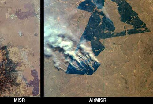
These images of northeastern South Africa, near Kruger National Park, were acquired on September 7, 2000. The left image shows an 85-kilometer wide x 200-kilometer long area captured by MISR's aftward- viewing 45-degree camera. At lower left are the Drakensberg Mountains; to the east of this range a large burn scar with thin smoke plumes from still-smoldering fires is visible. Near the top of the image another large burn scar with an open-pit mine at its western edge can be seen. Other burn scars are scattered throughout the image.
Just above the center of the lefthand image is a polygonal burn scar with a set of smoke plumes from actively burning fires at its southwestern tip. The righthand image, which is a "zoomed-in" view of the area, was acquired almost simultaneously by MISR's airborne counterpart, AirMISR, aboard a NASA ER-2 high-altitude aircraft. AirMISR contains a single camera that rotates to different view angles; when this image was acquired the camera was pointed straight downward. Because the ER-2 aircraft flies at an altitude of 20 kilometers, whereas the Terra spacecraft orbits the Earth 700 kilometers above the ground, the AirMISR image has 35 times finer spatial resolution. The AirMISR image covers about 9 kilometers x 9 kilometers. Unlike the MISR view, the AirMISR data are in "raw" form and processing to remove radiometric and geometric distortions has not yet been performed.
Fires such as those shown in the images are deliberately set to burn off dry vegetation, and constitute a widespread agricultural practice in many parts of Africa. These MISR and AirMISR images are part of an international field, aircraft, and satellite data collection and analysis campaign known as SAFARI-2000, the Southern Africa Regional Science Intitiative. SAFARI-2000 is designed, in part, to study the effects of large-scale human activities on the regional climate, meteorology, and ecosystems.
Image Credit: NASA/GSFC/JPL, MISR and AirMISR Teams. Catalog No. PIA02624
Like MISR, AirMISR was a 'pushbroom' sensor, which imaged a cross-track slit beneath it during each scan. A two dimensional scene is built up by successive scans as the spacecraft or aircraft fly over the scene. While MISR has nine cameras which image the earth continuously, AirMISR's single camera was swiveled to successive look angles to complete a desired set of multi-angle images.
This means that AirMISR, unlike MISR, only produced a complete multi-angle image set over a single patch in the middle of the imaging run.
Performance Specifications
Camera Specifications
| Number of active pixels | 1504 per band |
|---|---|
|
Cross track field of view (swath width) |
29.8° |
| Along track instantaneous field of view (IFOV) | 0.3 milli-radians |
| Spectral bands: |
446.4 nm (blue), 557.5 nm (green), 671.7 nm (red), 866.4 nm (near-IR), |
| Bandwidths: | 41.9 nm, 28.6 nm, 21.9 nm, 39.7 nm |
| Out-of-band/in-band ratio: | 0.8%, 2.3%, 4.9%, 1.8% |
| Digitization: | 14 bits |
|
Radiometric calibration absolute uncertainty: |
5% (1 standard deviation), at maximum signal |
| Signal to Noise Ratio (SNR) | > 900, excluding anomalous pixels |
| Viewing angles |
9, identical to MISR; ±70.5°, ±60°, ±45.6°, ±26.1°, and 0° (nadir) |
Platform/Instrument Specifications based on nominal ER-2 operating parameters
| Flight altitude | 20.5 km above mean sea level (MSL) |
|---|---|
| Ground speed | 204 meters/second |
| Duration of imaging run | 12 minutes |
| Length of imaging run | 148 km |
| Maximum number of runs per flight | >14 |
| Maximum flight duration | >6.5 hours |
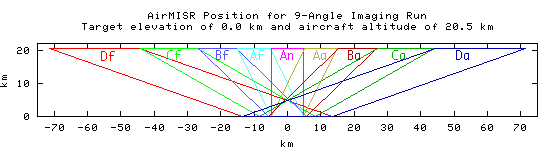
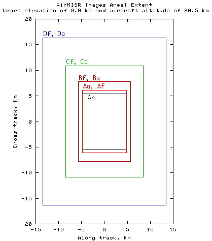
The spatial resolution and extent of each AirMISR scene depends upon the aircraft altitude and target elevation. For a target at sea level, the following table (and figure) shows the coverage of each of the nine images acquired in a run.
| Camera Angle | |||||
| Df,Da, ±70.5° |
Cf,Ca, ±60° |
Bf,Ba, ±45.6° |
Af,Aa, ±26.1° |
An, nadir, 0° | |
|---|---|---|---|---|---|
| Swath Width (km) | 32.7 | 21.8 | 15.6 | 12.1 | 10.9 |
| Along track image length (km) | 27.0 | 17.0 | 11.3 | 9.6 | 9.6 |
| Cross track pixel size (m) | 21.7 | 14.5 | 10.4 | 8.1 | 7.3 |
| Along track pixel size (m) | 55.8 | 24.9 | 12.7 | 7.7 | 6.2 |
| Line spacing (distance traveled between scans) | 8.3 m, for all angles | ||||
| %Overlap/Underlap (gap) | 85% | 67% | 35% | -8% | -34% |
To simplify requirements on the end user, and to maintain commonality with MISR algorithms, the standard AirMISR data processing normalized all images to 27.5 meter resolution, 10% of the MISR resolution. The images were also georectified, with North at the top, and the effects of aircraft motion were removed to the extent possible.
AirMISR Data Quality
Each of the AirMISR data sets available from the Atmospheric Sciences Data Center (ASDC) include product-specific data quality statements. Most of these statements can be represented by the following generalized summary statements.
Radiometric Accuracy
The radiometric calibration of AirMISR was done using the same procedures as used to calibrate the MISR cameras. Cross-comparison studies with MISR, Landsat and Vicarious Calibration studies indicate AirMISR had a 5% bias as compared to other sensors, reporting higher radiances.
Vertical striping may at times be viewed in AirMISR imagery. These are insignificant in terms of radiance variability, as they are typically on the order of 0.5%.
One difference between MISR and AirMISR radiometric performance is the camera-relative uncertainty, which was smaller for AirMISR in that this aircraft sensor consisted of only one gimballed camera. Thus, errors at one view angle, relative to another are not present. This is not the case for MISR, which makes use of nine cameras to acquire the mult-angle data.
The values quoted for the systematic component of the radiometric uncertainty, based on vicarious calibration of the instrument, in fractional units, are
- abs_sys_error = 0.050
- cam_sys_error = 0.000
- band_sys_error = 0.010
- pixel_sys_error = 0.005
These systematic components are combined with the signal-to-noise ratio (SNR), to determine the total error uncertainties. As SNR is signal dependent, the uncertainties are likewise signal dependent. The SNR, at two radiance input levels, are as follows
- SNR(at an equivalent reflectance of 1.0) ~ 1000
- SNR(at an equivalent reflectance of 0.05) ~ 200
Using these, the total radiometric uncertainties can be determined
- abs_total_error=sqrt(abs_sys_error2+(1/SNR)2)
- cam_total_error=sqrt(2)/SNR
- band_total_error=sqrt(2)*sqrt(band_sys_error2+(1/SNR)2)
- pixel_total_error=sqrt(2)*sqrt(pixel_sys_error2+(1/SNR)2)
Ghost image effects
The MISR and AirMISR camera designs share a common heritage, hence performance evaluation studies conducted for one are also applicable to the other. The radiometric accuracy for the MISR cameras are described in Bruegge, et al. (2002). One such study, involving AirMISR and MISR data sets acquired over the Chesapeake Lighthouse, August 2001, showed signal-dependent radiance ratios. This has been attributed to ghost-image effects, in which light from the brighter land is reflected into the darker ocean portions of the scene. The darker targets have proportionally greater radiometric error due to these effects. AirMISR was less sensitive to such errors, in that scene uniformity over the 10 km swath is typically greater than observed for the 380 km MISR swath widths. Thus background contamination of the signal was less for AirMISR.
AirMISR Geometric Data Quality
AIrMISR geolocated and co-registered radiance data sets (Level 1B2 products) were produced by initial, manual, and automated algorithms. The manual process was used for the majority of products delivered to date.
For the manual L1B2 product, the geometric calibration was performed prior to orthorectification to the UTM map projection grid. A set of ground control points collected from US 124000 topographic maps were used to improve geometric data quality. These points were identified in AirMISR imagery in order to remove static errors in the camera pointing and airplane position. Only runs taken over clear land were used for ground control point identification. Geolocation errors of about 1000 meters for nadir view to up to 6000 meters for the most oblique view (for the initial L1B2 product) were reduced down to an average of about 150 meters regarding both absolute geolocation and coregistration between nine view images. The remaining errors can be regarded as a result of the dynamic errors in airplane attitude and position which are not modeled in the current calibration algorithm.
Applications of AirMISR Imagery
AirMISR has been employed to radiometrically calibrate the MISR cameras, to measure directional reflectance characteristics of soils, vegetation, snow, and clouds, and to measure the amount and type of aerosols in the atmosphere.
AirMISR served as a surrogate MISR, with the capability to revisit a scene more frequently than the Terra satellite's 16 day repeat cycle, or on days during focused investigations in which weather conditions were ideal but no satellite overpasses were scheduled. AirMISR was used to explore other sun angles, azimuths, or timing than those possible with MISR. The instrument was also flown with other airborne instruments, such as sounders, profiling LIDARs, hyperspectral scanners, or other EOS instrument simulators, etc., to provide a comprehensive dataset on a single scene.
Here are a few published papers that have used AirMISR data.
Organizations and Responsibilities
The Jet Propulsion Laboratory (JPL) operated and maintained the AirMISR instrument for NASA, and processed the data into georectified radiance products as part of the MISR data processing task. JPL was responsible for scheduling the instrument, staffing field campaigns, repairing, maintaining, calibrating, and upgrading the instrument, and delivering the final data products to the investigator and to the Langley Atmospheric Sciences Data Center DAAC, where they were made available publicly. Most of the costs of this activity were borne by the EOS/MISR program, as part of the calibration & validation effort for the satellite instrument. JPL can also assist in identifying MISR overpasses and existing datasets, and has some ground instrumentation that may be of interest to investigators.
NASA's Armstrong Flight Research Center operates the ER-2 aircraft in conjunction with NASA Headquarters. NASA Armstrong schedules the use of the ER-2 aircraft to maximize the science return among multiple instruments or users and within budget and staffing constraints. Armstrong also provides the aircraft pilots, maintenance crew, and mission managers who plan and execute campaigns.
Data Processing & Distribution
After the flight, a preliminary examination of the images obtained was performed in the field. This was intended to verify that the camera operated properly, to assess whether the target was acquired at all nine view angles, and determine the presence or absence of clouds in the scene. The original raw image files, along with navigation data and engineering data recorded in flight, were sent back to the MISR Science Computing Facility (SCF) at JPL for processing and distribution.
The processing results in a set of radiometrically corrected and georectified images, resampled to a uniform resolution, stored in Heirarchical Data Format (HDF) files. The data was sent to the NASA Langley Atmospheric Sciences Data Center (Distributed Active Archive Center), where it is permanently archived and made available for other researchers.
The steps involved in the processing were:
- Resampling the recorded navigation data, including aircraft position and attitude, to a uniform 64 Hz time resolution.
- Converting the raw digital numbers stored in the image files into radiometric values by applying the latest calibration coefficients for each pixel in the AirMISR camera. The outcome of this is termed a "Level 1B1" product, which is spectral radiances stored in HDF format. Browse images are also produced at the full resolution of the AirMISR camera, but not corrected for aircraft motion.
- The images are then projected onto a terrain model, and resampled to a uniform 27.5 meter resolution on a Universal Transverse Mercator (UTM) projection. This involves both automated routines and manual identification of tie-points from LandSat imagery that can improve the geo-rectification. These images are "Level 1B2" products.
- Additional processing can be performed to locate target points within the images, to produce browse images or RGB composites, or to convert the images to ERDAS Imagine® or other formats.
Requesting Existing AirMISR Data
AirMISR operated between 1998 and 2004, for various campaigns across the continental US, Alaska, and in South Africa. Some of the early data acquisitions were affected by various instrument problems that were fixed in later deployments. The highest quality AirMISR datasets were sent to the Atmospheric Sciences Data Center for archival and distribution. The ASDC provides browse images, a description of the data quality, and instructions on how to order these datasets.
Contacts
- Email AskMISR