MISR Instrument
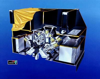
This is an artist's rendition of the MISR instrument in cutaway view. The back ends of the 9 MISR cameras appear as yellow cylinders. In this orientation, MISR would look down toward Earth.
JPL image P-44988
The Multi-angle Imaging SpectroRadiometer (MISR) instrument provides a unique opportunity for studying the ecology and climate of Earth through the acquisition of global multiangle imagery on the daylit side of Earth.
There are many requirements that must be taken into account when designing an instrument like MISR. This section describes some of them, i.e. rationale for why MISR is designed the way it is. For example, it tells why there are nine cameras and why they are set at particular angles.
The following paragraphs are by no means a full specification of the instrument. However, they represent some of the major items, and it is hoped that this will give the reader an indication of the types of unique factors considered when an instrument of this kind is conceived. The section begins with a summary of the engineering specifications of the instrument and, for completeness, of the Terra spacecraft on which MISR is flown.
To read an article about building an on-orbit sensor such as MISR, click here.
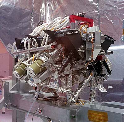
This is the "science part" of the MISR instrument, which includes the cameras and calibration equipment. The photograph was taken in October 1996, as MISR was being assembled. Subsequently, the parts that supply power, communications, and temperature control were added. The entire package was then encased in a protective housing, which was covered with highly reflecting thermal blankets.
JPL Image P-28109A
Specifications of the MISR Instrument
| Design life: | As designed; mission is still ongoing |
|---|---|
| Instrument mass: | 148 kg |
| Instrument power: | Approximately 117 W peak, 75 W average |
| Data rate: | 3.3 Megabits/second average, 9.0 Megabits/second peak |
| Global coverage time: | Every 9 days, with repeat coverage between 2 and 9 days depending on latitude |
| Crosstrack swath width: | About 400 km common overlap of all 9 cameras |
| Nine pushbroom cameras: | Named An, Af, Aa, Bf, Ba, Cf, Ca, Df, and Da where fore, nadir, and aft viewing cameras have names ending with letters f, n, a respectively and four camera designs are named A, B, C, D with increasing viewing angle respectively |
| View angles: | 0, 26.1, 45.6, 60.0, and 70.5 degrees |
| Spectral coverage: | 4 bands (blue, green, red, and near-infrared) |
| Detectors: | Charge Coupled Devices (CCDs), each camera with 4 independent line arrays (one per filter), 1504 active pixels per line |
| Radiometric accuracy: | 3% at maximum signal |
| Detector (focal plane) temperature: | -5 ± 0.1 degrees C (cooled by thermo-electric cooler) |
| Temperature of main structure: | +5 degrees C |
| Builder: | Jet Propulsion Laboratory, Pasadena, California, U.S.A. |